A flying probe tester is an automated test system which some specific advantages for particular applications.
The Basics
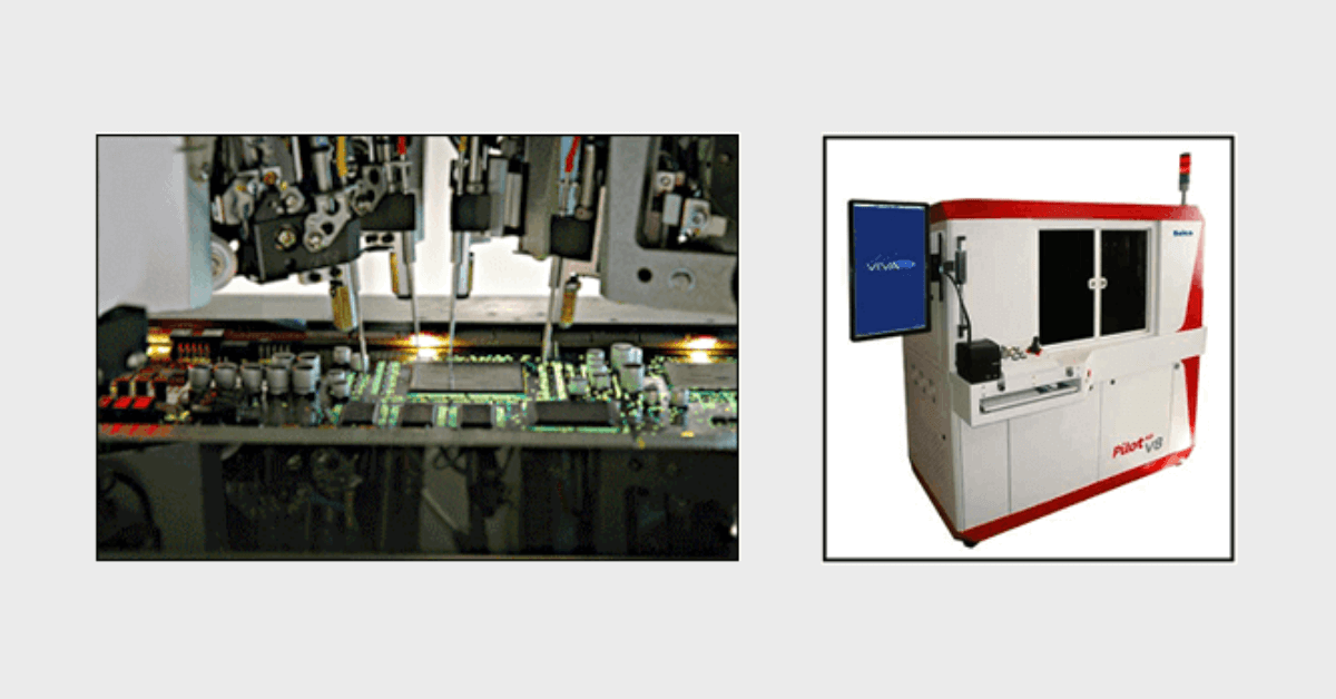
Flying probe testers avoid a custom, unique “bed-of-nails” fixture for a given PCB assembly to access all the required nodes . Rather, the system uses a generic board fixture, and one or more probes moves across the board to access accessing individual nodes via software control.
The main advantages of a flying probe tester is elimination of custom, fixed test it’s also much easier to introduce changes as only the control software needs revision. Flying probe type testers include basic capabilities (opens, shorts, basic component tests) as well as on-board memory module programming and boundary scan testing so they can rival the capabilities of advanced ICT systems.
Another advantage of flying probe testers is that test probes can be placed very accurately enabling them to be placed on small pads, component solder connections and PLCCs, SOICs, PGAs, SSOPs, QFPs IC types.
| Advantages | Disadvantages |
|---|---|
| Elimination of custom, hard fixtures | Slower operating speed |
| Flexibility to handle changes | Limitations on complicated tests |
| Test development time is reduced as the software can be developed quickly from PCB design files |
Flying probe test system, are well suited for prototype and small volume production. They are generally considered not as suitable for volume production applications, unless used on a sample basis.
Flying probe testers are generally used as they provide a much more cost-effective and flexible form of In-circuit test. While flying probe testers have some limitations, their flexibility, low development costs and short development times are well suited for low volume production environments.