Basics of an ICT test system
An ICT tester consists of
- Controller – The controller is a computer to drive the system and run the required software.
- Switch – Routes the system to the specific area or node of the board to test.
- Interface – To allow a variety of board fixtures to be placed onto the tester. This includes the electrical connection, may include power if the board is to be powered and possibly an air supply or vacuum if the board is to be pulled down onto the “bed of nails”
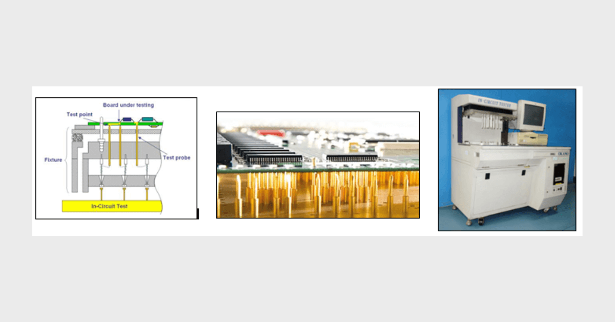
- Fixture – “bed of nails” or spring loaded test pins performs the physical contact with the unit under test.
Driver-sensors
The active circuits used for performing measurements. Drivers and sensors are present in pairs. Drivers supply voltage or current to enable a node in the circuit to be driven to a particular state. They have high capability to enable the node to be driven to the required state despite the condition of surrounding circuitry. Typically they may need to force the output of a digital IC to a given state despite the natural output state of the device. To achieve this the output impedance of the driver must be very low.
Sensors make the actual measurements. These need to have a high impedance so that they do not disturb the circuit being measured.
Guarding
It’s easy to measure the value of a component when it is not in a circuit. However, when in a circuit there are components which may alter the value of the item to be measured. To address this problem and increase the accuracy of measurement, guarding is used to connect other parts to earth ground so leakage paths are removed and more accurate measurements made.
Multiplexing
For complicated or larger printed circuit assemblies the total node count may exceed the capability of the test system. To dedicate pins for each node can be very costly as each also requires a sensor. Multiplexing can be used whereby a particular node can be placed through a switching matrix to address more than one node. Only one multiplexed node can be accessed at a time so multiplexing limits programming and fixture design.